
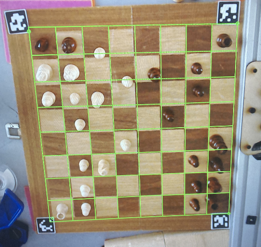
The first step in identifying what piece the player moved is being able to determine where the board is. Apriltags are placed at three corners of the board, which are used to estimate the square that forms the edges of the board. From there, this square is evenly divided into an 8x8 grid, which allows us to look at each square of the board individually.
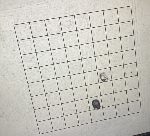
From there, the image of the board immediately before the player moves is compared to the image of the board immediately after the player moves. The difference between these two images is calculated using the structural similarity index function from scikit-image.
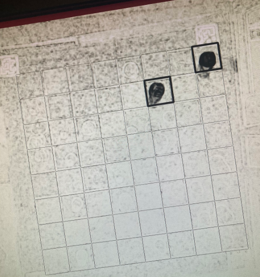
From there, the previously calculated grid of board squares is used to figure out what squares the piece moved from/to. The two squares on the board that have the highest difference between before and after the player’s move must be the squares that the piece moved from/to.
The remaining question is determining which square the piece started on and which it ended on. We decided that both the simplest and most consistent way to determine this would be not using the camera but instead comparing with the saved board state variable. Of the two squares that the piece moved between, only one could have had one of the player’s pieces on it before the player moved - you can’t move a piece to a square already occupied by one of your own pieces. Using this logic, the full player move can be determined.
We decided to use BettaFish as our chess engine that provides moves for the WidowX-200 arm to play, BettaFish is a Discrete Mathematics final project developed by Eddy Pan, a member of this Chess Robot Arm Player, and three other students—Sam Wisnoski, Bill Le, and Daniel Theunissen. BettaFish uses a Minimax Algorithm to a depth of 5 to pick its next move. BettaFish is equipped with Alpha-Beta Pruning—an optimization technique that immensely improves computation time
To evaluate board positions, BettaFish uses an evaluation function that takes material and piece activity (through piece-square tables) into account. Overall, expect BettaFish to play with an ELO of ~1700 on chess.com—a chess platform that hosts the largest playerbase online. For context, a 1700 ELO is roughly around the 87-98th percentile of all chess.com players. This ELO has been approximated through its performance playing against the other levels of bots on chess.com. BettaFish was able to beat Isabel, a 1600 ELO rated bot, but suffered a defeat to Wally, an 1800 ELO rated bot.
BettaFish boasts an aggressive but tactical playstyle, often winning games by taking advantage of its opponents mistakes; however, it’s also important to note that BettaFish isn’t yet fully cognizant of draws by repetition…
How we interpreted, abstracted and leveraged the physical platform we ran our package on.
Kinematic arm theory is a branch the robotics that deals with geometric relationships between the various components of a robotic arm, and how the components can work together to change the position of the end effector.
While controlling a robotic arm it’s important for the robot to be able to keep track of all of it’s joints positions and orientations. It’s also important for it to predict how changing its joints will change the position of it’s end effector. Kinematic arm theory provides a structure to represent the position in computationally efficient matrices, constrain the arm based on its joints relationships therefore identify the transformation necessary to get from one position to the desired position and then make movements that will actualize that transformation.
Overview: Forward arm kinematics refers to the mathematical process of determining the positions and orientations of a robotic arm's links and end-effector based on the known joint parameters and the robot's kinematic structure.
This is distinct from parallel kinematics, where the position of the end-effector is determined by the combined influence of multiple, interdependent joint systems. In serial kinematics, like those used in most robotic arms, the arm is a sequential chain of joints and links. Each joint and link adds to the overall position and orientation of the end-effector in a hierarchical fashion.
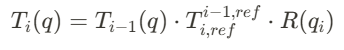
Forward kinematics is a mathematical way to use the joint parameters of a system to calculates the pose of it’s end effector. This is achieved by calculating the transform matrices for each link in the chain, which describe how the position and orientation change from one link to the next. The transformation for a link is a product of its parent link's transformation, a local reference transformation, and any movement induced by its joint. The forward kinematics of a robot can be mathematically derived in closed form, or can be computed in a software library for tasks like motion prediction, collision detection, or rendering.
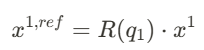
The general recursive equation for forward arm kinematics can be written as:
This equation uses the movement of point x on a linkage (l_i) to solve for the change of the frame of the first link (T_1) with respect to an angle change (q).
Derivation of a single joint:
To understand the transformation for one link in detail, consider the motion of a point x on a link l_i. The change in coordinates from the link's local frame to the global frame involves a rotation and translation.
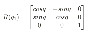
Rotation:
A revolute joint rotates the link by an angle q_i
For 2D rotation, the rotation matrix R(q) is:
Coordinate Conversion: The local coordinates of the link are translated into the parent link's coordinate frame by applying the reference transformation matrix.
Recursive Transformation: To express the link’s pose in the global frame, the parent's transform Ti−1Ti−1 is applied.
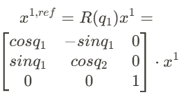
The following relationship:
describes a system that has n links and revolute joints l_1, … l_n and j_1, … j_n respectively with the angles between them being q_1 … q_n. In this system the links coordinate frames are defined by their reference transforms at 0. Each of these coordinate frames are expressed relative to their coordinate systems. which are expressed by their homography.
This equation has three clear parts
1) Rotation about the joint
- Represents the rotation caused by the joint i
- Converts the coordinates of the current link from its moved frame to its reference frame.
2) Conversion to the coordinates of the parent link
- Translates and rotates the current link into the coordinate frame of its parent link.
3) Transformation by the parents transform
- Maps the parent link’s frame to the global frame
The WidowX use the Interbotix Python API to abstract its kinematics and provide high-level commands to control the robot. The API is able to do this by providing 3 major kind of movement commands:
1) Pre-planned poses
- The API allows the user to save joint positions and send the arm to specific configurations without requiring manual calculations
2) Cartesian control
- The API let users define the end-effector position in Cartesian space (e.g., x, y, z), and automatically handles the inverse kinematics.
3) Trajectory control
- The API provides motion planning between waypoints.
The WidowX a library called MoveIt to handle motion planning and joint transformations.
Since this was an application-based project, we didn’t want to spend an excessive amount of time on creating our own custom interface with our WidowX robot arm, so we decided to base our computational setup on the repository below. This setup abstracts much of the lower-level control of the robot, including inverse kinematics and gripper pressure limits for object manipulation.
https://github.com/rail-berkeley/bridge_data_robot
This setup builds a docker container that has all the dependencies required for the lower-level abstractions. By running the robot as a server (which is done through the container), and then running a client script in a separate terminal, the user is able to send commands to the robot through Python functions.
There are 3 functions through which you can interact with the robot. The first command is move(), which takes an input numpy array of length 6 (x,y,z,roll,pitch,yaw), and moves the robot to that position. The second command, move_gripper(), ****takes an input float or integer from 0 to 1 and moves the gripper to that position (1 is fully open, 0 is fully closed). The last command, step_action(), takes an input array of length 7 (x,y,z,roll,pitch,yaw,gripper), moves the robot incrementally by that amount, and moves the gripper to the position specified. So (0,0,0.1,0,0,0,0) would move the end effector 0.1 meters in the positive Z direction and close the gripper if it was opened.
We had to make several significant modifications to this setup to get it to run properly, which was a major time sink in the early stages of the project. These changes included removing all mentions of cameras from the server (to solve issues with reading from cameras), requiring specific versions of certain libraries in the Docker container, and modifying the gripper controller to allow any amount of openness or closed-ness (instead of just fully open or fully closed). These modifications allowed us to effectively and reliably interact with the robot with relative ease.
Pick-and-Place This function takes a start point and end point (in XY coordinates), the height required to grasp the object, and the clearance height required for the move, and the robot then picks up an object located at the start point and places it at the end point. The function also contains several features that allow it to work quickly and repeatably for any starting and ending locations on the board.
One major feature that this function has is droop calibration. During our testing, we realized that as the arm joints were extended farther away from the base, they tended to “droop”, leading to a lower end-effector position at the same Z-height. In order to solve this, we empirically tested this droop at various points across the chessboard, and created a transfer function between them.
This Python module's purpose was to find the pose of the centers of each of the four corner squares of the chess board (A1, H1, A8, H8) by trial-and-error. To accomplish this goal, we took an initial guess of where the center of one of the corner squares would be, then stepped around it until we reached an accurate pose of the corner.
A Chess board is composed of files (a, b, c, d, ..., h) and ranks (1, 2, 3, .., 8). With the poses of each of the corners, we knew the chess.Board() object provided from python-chess starts with an index of 0 at a1, so we considered a1 to also be our 0th index square, and h8 our 63rd index square. We took the difference of the distance from the a1 to a8 poses, which represented our file distance, and divided it by 7 to get our file step size. We mimicked this process for the a1 to h1 poses, which represented our rank distance, to get the rank distance. We used these two step sizes in tandem to have the arm step through the poses of each of the squares on the chess board by starting at a1, stepping through all the files until it reaches h1, then moving to a2 and repeating the process until it reached h8. We saved each of these pose's locations to a list of 63 (x,y) tuples, which would then be used in our main game file, bot.py.
Our Python file has gone through a couple of development cycles.
#1 At first, we programmed the arm to just play moves provided by the player in a command line GUI using the aforementioned pick-and-place function and the hard-coded poses for the board map we got from brute force testing. To create a virtual chess board in python, we use the python-chess module’s chess.Board() object.
#2 Next, we incorporated the BettaFish chess engine to decide which moves the bot would play. We still used a command line interface to provide the bot with the move the player played. On the bot’s turn, we would plug the current board state into the chess engine, and the arm would play the move BettaFish selected.
#3 To fully remove the command line interface, we used computer vision with AprilTags to (1) draw a geographical map of the board’s squares. Then, using the known relative pose of the camera compared to the board from the arm, we triangulated the positions of each square—therefore no longer relying on the board staying in the same relative position as the arm. Additionally, by incorporating computer vision, we (2) were able to reduce the user input; instead of the user providing the move they played to the algorithm by typing in chess notation, we can recognize which piece moved, and since the location of all the pieces on the board are stored in the chess.Board() object, we can reference which piece moved.
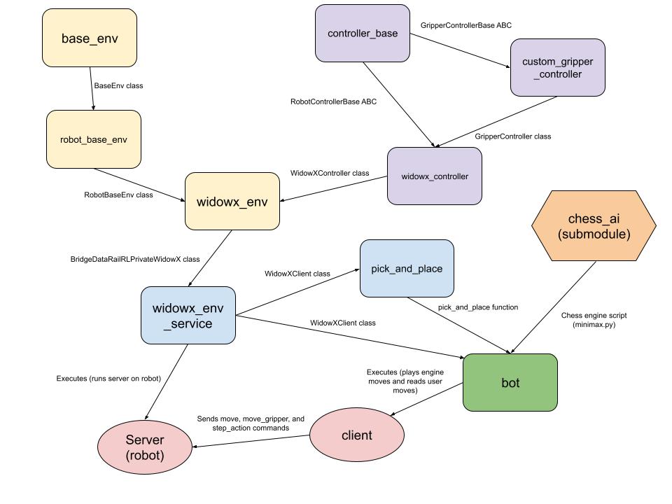
The diagram above shows all the core components that make up the Chess Bot and the data that flows between them.
base_env:
Initializes a class for a high-level base environment for robotics or simulation applications.
robot_base_env: Initializes a class that inherits from base_env with functionality specific to robotics applications.
controller_base: Initializes abstract base classes for creating a controller for a robotic arm and a controller for a gripper end effector.
custom_gripper_controller: Initializes a class for controlling the default WidowX end effector that inherits from GripperControllerBase.
widowx_controller: Initializes a class for controlling the full WidowX robot arm. This class inherits from the RobotControllerBase class. This class creates an instance of GripperController that serves as the controller for the arm’s end effector. This class also contains the code for inverse kinematics abstraction.
widowx_env: Initializes an environment for interacting with the WidowX arm. This class inherits from the RobotBaseEnv class, creates an instance of WidowXController, and provides additional functionality for starting up and resetting the robot.
widowx_env_service: Creates WidowXActionServer and WidowXClient classes, which allow Python scripts to interface with the robot by running an instance of WidowXActionServer and then creating an instance of WidowXClient in a separate script.
pick_and_place: Creates a function for picking up an object at a certain location and placing it at another location using commands in the WidowXClient class.
chess_ai: This is a submodule that contains the chess engine that the bot uses to calculate its next move, which is located in the file minimax.py.
bot: This file is the executable that reads the user’s moves, calculates the next move, and plays that move on the physical board.
This site was created with the Nicepage